Magnetic Limit Switch Wiring Diagram
52 Fantastic Magnetic Switch Wiring Diagram. GO Switch models 11 21 31 and 81 are the ideal replacements for traditional mechanical limit switches.
 My First Time Wiring Up Magnetic Switch And Test Circuit After Snipping And Stripping Wire Youtube
Magnetic switch wiring diagram Whats Wiring Diagram.

Magnetic limit switch wiring diagram. A wiring diagram is a kind of schematic which uses abstract pictorial symbols to exhibit every one of the interconnections of components in the system. Electric Gate Motor Wiring Diagram and How Do I Connect A Direct On Line Dol Starter To A Single. Separate Control 95 Reset L1 L2 L3 1 3 5 T1 T2 T3 T1.
Two-hand control switch S4 S5. 5 Most limit switches contain the following functional parts in one form or another. Sealed contacts rugged housings non-contact detection of ferrous metal magnetic targets and snap action response.
Assortment of magnetic switch wiring diagram. If a switching output is strictly PNP or NPN the external connection through the loadThanks for purchasing our inductive Proximity Limit Switch Kit. Low voltage wiring can enter through the right or left side of refer to the appropriate wiring diagram for the unit being serviced.
A wiring diagram is a streamlined conventional photographic depiction of an electrical circuit. A simple video on how to wire up the limit switch. TD03309004E For more information visit.
It reveals the components of the circuit as simplified shapes and also the power as well as signal connections in between the tools. 1 strong magnetic fields 2 extreme temperature and 3 excessive ferrous filing or chip buildup. In the most basic system this functionality is provided by use of a fan center relay and the low voltage wiring to the thermostat now will require a minimum of three wires for heat only units and four wires for heat cool fan for control.
In some limit switches the actuator. Wiring and diagram for a Float Switch water level switch for water pump control in tagalog Local Electrician Thank you for watching guys. Reset switch S31 S32.
Limit Switch Wiring Diagram Motor Source. L sal r. Download this article as a PDF 00-02-0257 Typical Wiring Diagram with 117117PH Magnetic Switch Typical Wiring Diagram with MS2100 TATTLETALE Typical Wiring with 518E models Typical Wiring Diagram with 760A and.
Typical Wiring Diagram with 117117PH Magnetic Switch Typical Wiring Diagram with MS2100 TATTLETALE MurCac l CALL MURCAL TO PLACE YOUR ORDER P661272-4700 F661947-7570 w w wem- m. Improper wiring may damage or destroy the switch. Magnetic Switch Wiring Diagram Download - Safety Circuit Examples Of Safety Ponents.
Proximity Switch Symbol The schematic diagram symbol for a proximity switch with mechanical contacts is the same as for a mechanical limit switch except the switch symbol is enclosed by a diamond shape indicating a. Electric Gate Motor Wiring Diagram and Gate Ga Circuit Board Connections Diagram Access. Safety limit switch with direct opening mechanism KM1 KM2.
Variety of magnetic door switch wiring diagram. A wiring diagram is a simplified standard pictorial representation of an electric circuit. Ted Crocker Wiring Diagram 1 Single Coil 2 Piezo 1 Vol 3 Way.
Electric Gate Motor Wiring Diagram and Sliding Gate Magnetic Limit Switch Sensor Wiring. Emergency stop switch with direct opening mechanism S2. The following instructions go over the hardware and software settings required to set up Homing including auto-squaring of your gantry for dual-drive machines and Limits with our inductive proximity switches.
ActuatorOperating Head The actuator is the part of the switch which physically comes in contact with the target. Magnetically operated limit switches should not be subjected to. April 2007 Page 5 Basic Wiring for Motor Contol Circuitry of a Starter Figure 5.
It shows the components of the circuit as simplified shapes and also the.
 Add Up Down Momentary Switches To Harbor Freight Hoist Doityourself Com Community Forums
 Safety Circuit Examples Of Safety Components Technical Guide Australia Omron Ia
 Linear Actuator Wiring Diagram Using 2 Limit Switches Provided In Each El Kit Linear Actuator Actuator Switch
 Motor Forward Reverse Wiring Diagram Elec Eng World Electrical Circuit Diagram Basic Electrical Wiring Electrical Wiring
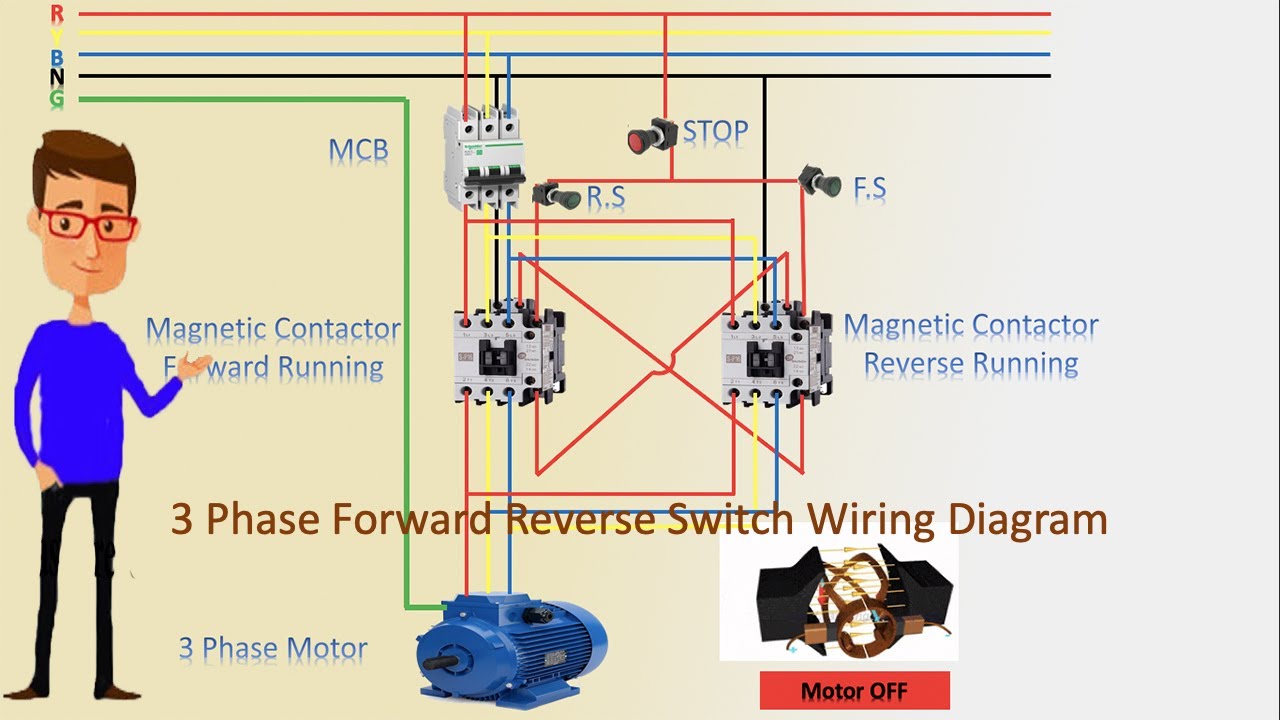 3 Phase Forward Reverse Switch Wiring Diagram Contactor Wiring Motor Wiring Youtube


