Braeburn Thermostat Wiring Diagram
Braeburn thermostat wiring diagram BRAEBURN 1020NC Thermostat Non Programmable 1H 1C. Fasten sub-base to wall using supplied screws into the plastic wall anchors.
 Unique Honeywell Thermostat Th8321u1006 Wiring Diagram Diagram Diagramsample Diagramtemplate Honeywell Wifi Thermostat Heater Thermostat Thermostat Wiring
It reveals the components of the circuit as streamlined forms and also the power and also signal links in between the tools.

Braeburn thermostat wiring diagram. Literally a circuit is the path that enables electrical power to circulation. 2 HEAT 2 COOL Single or Dual Transformer 1220 Only. Obtaining from factor A to point B.
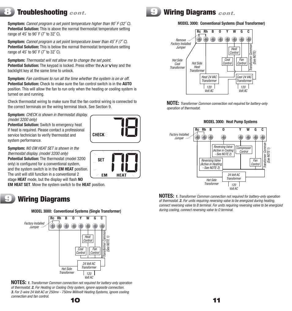
Braeburn 7320 universal programmable smart wi-fi thermostat for systems up to 3 heat 2 cool with wireless humidity control 40 pages Thermostat Braeburn 5200 Owners Manual Premier series 7-day programmable 2-heat2-cool heat pump digital thermostat 11 pages. Conventional Systems Dual Transformer Symptom. April 21 2020 by Larry A.
Braeburn thermostat wiring diagram A Newbie s Overview of Circuit Diagrams. 3200 thermostat pdf manual download. Braeburn thermostat Wiring Diagram.
Turn the thermostat body over exposing the rear view of the circuit board. Wiring Diagrams Troubleshooting Wiring Diagrams cont. Hooked it up to a Rudd heat pump unit.
How to wire a braeburn model thermostat to a ruud model rgeaajdaa. Premier Series Non-Programmable 2 Heat 2 Cool Heat Pump Digital Thermostat. Today I want to talk about how simple a thermostat really is how the common and hot wire goes to a transformer how you tie the white wire for the heat stri.
York E1 Series Typical Heat Pumps THERMOSTAT TERMINAL BLOCK User Supplied Jumper Braeburn Systems LLC warrants each new Braeburn thermostat YEAR against any defects that are due to faulty material or workmanship for a period of two years after the original date of LIMITED purchase by a professional service technician. A wiring diagram is a simplified traditional pictorial representation of an electrical circuit. Use the wiring diagram chart to insure the old and new connections are correct.
Place the thermostat sub-base against the wall in the desired location making sure the mounting holes are aligned and the thermostat wires are inserted through opening in sub-base. View and Download Braeburn 3200 user manual online. 4 NOTES - Conventional Systems 1 If batteries are installed the 24 Volt AC common connection is optional 2 Remove factory installed jumper for dual transformer systems 3 In dual transformer systems transformer common must come from cooling transformer 4 If needed for system.
Use the wiring diagram chart to insure the old and new connections are correct. 4 NOTES - Conventional Systems 1 If batteries are installed the 24 Volt AC common connection is optional 2 Remove factory installed jumper for dual transformer systems 3 In dual transformer systems transformer common must come from cooling transformer 4 If needed for system Provide disconnect and overload protection as required. Braeburn 7320 universal programmable smart wi-fi thermostat for systems up to 3 heat 2 cool with wireless humidity control 40 pages Thermostat Braeburn 5200 Owners Manual Premier series 7-day programmable 2-heat2-cool heat pump digital thermostat 11 pages.
2 HEAT 1 COOL Single or Dual Transformer 1220NC Only. Turn the thermostat body over exposing the rear view of the circuit board. This section contains various Braeburn Thermostats for heating and cooling.
Braeburn Thermostat Wiring Diagram Fasten sub base to wall using supplied screws into the plastic wall anchors. Connect wires to quick wiring terminal block as appropriate using the new. The temperature sensed by the thermostat is higher than the 99 F 37 C upper limit of the thermostats display range.
To prevent electrical shorts and potential damage to the thermostat make sure all wire connections are secure and not touching each other. This is above the normal thermostat temperature setting Rc Rh range of 45 to 90 F 7 to 32 C. Turn on the cooling system or use other methods to lower the temperature.
Variety of braeburn thermostat wiring diagram. Need diagram if possible wiring a new - Answered by a verified HVAC Technician. To prevent electrical shorts and potential damage to the thermostat make sure all wire connections are secure and not touching each other.
Wiring Diagram Pics Detail. Page 11 WIRING DIAGRAMS cont. To prevent electrical shorts and potential damage to the thermostat make sure all wire connections are secure and not touching each other.
An initial look at a circuit layout may be confusing however if you could check out a metro map you could review schematics. Provide disconnect and overload protection as required. I have no diagram.
How to use Braeburn Thermostat. Cannot program a set point temperature higher than 90 F 32 C. The display will return to normal after the sensed temperature lowers within the 40 to 99 F 4 to 37 C display range.
 Braeburn Wiring Diagram 92 Lincoln Town Car Fuse Box Fords8n Yenpancane Jeanjaures37 Fr
 Troubleshooting Wiring Diagrams Braeburn 3200 User Manual Page 6 7
 18 Carrier Electric Furnace Wiring Diagram Carrier Furnace Thermostat Wiring Electric Furnace
 Great Gibson Heat Pump Thermostat Wiring Diagram Nordyne Heat Pump Heat Pump System Thermostat Installation Carrier Heat Pump
 Unique Wiring Diagram For Honeywell Thermostat Rth2300b Diagram Diagramsample Diagramtemplate Thermostat Wiring Honeywell Thermostat


